Clock

With transparent gears, wooden styling, and a giant pendulum this is a truly epic project. I learnt to design and model, test and fail, build and refine.
I designed the clock of 11 laser cut gears to use energy from a falling weight and timing from a swinging pendulum to tell time for 2 hours at a time.
This is an expanded model of my clock I built using Rhino and am displaying here using Fusion 360.
Mechanics
The ticking pendulum allows the escapement (first gear) to move a small amount each swing. Then the frequency of rotation is decreased to once per minute and connected to the second hand. then two pairs of gears decrease the frequency again to once per hour, which is connected to the minute hand. Finally another two pairs reduces it again to power the hour hand. In the middle of the minute to hour transition the weight is connected to provide torque to the whole system that causes the gears to rotate. The weight is attached via my personally designed ratchet, so that it can be rewound.
The pendulum is a threaded rod with a bob on it that can be screwed up and down. This changes the frequency of the the pendulum so that the clock can be tuned to minor accuracy.
Escapement
The escapement allows for the regular motion of the pendulum to regulate the movement of the clock. It also provides energy from the weight to power the pendulum so that air friction does not slow it. To achieve this the teeth on the escapement have a slope that the gear teeth push against.
The design of the escapement teeth allows the escapement to absolutely lock the rotation of the gear by shaping the teeth with a circular curve. The thickness of the escapement teeth had to be adjusted so that they were thin enough to avoid hitting the gear teeth.

Ratchet
I needed to attach the weight to a ratchet so it could be rewound without turning time backwards. So in typical style I decided to go through the unnecessarily complex (but much more interesting) route of designing my own novel ratchet.
The design has a inner and outer ring, with flexible bits of plastic (from packaging) attached to the inner ring that go to the sloped teeth in the outer ring. When the outer ring is turned counter clockwise (by the weight) the flexible plastic locks with the teeth and drives the inner ring and axle. If the outer ring is driven the other direction by hand the plastic slides over the teeth and the weight is wound up, without driving the axle backwards.
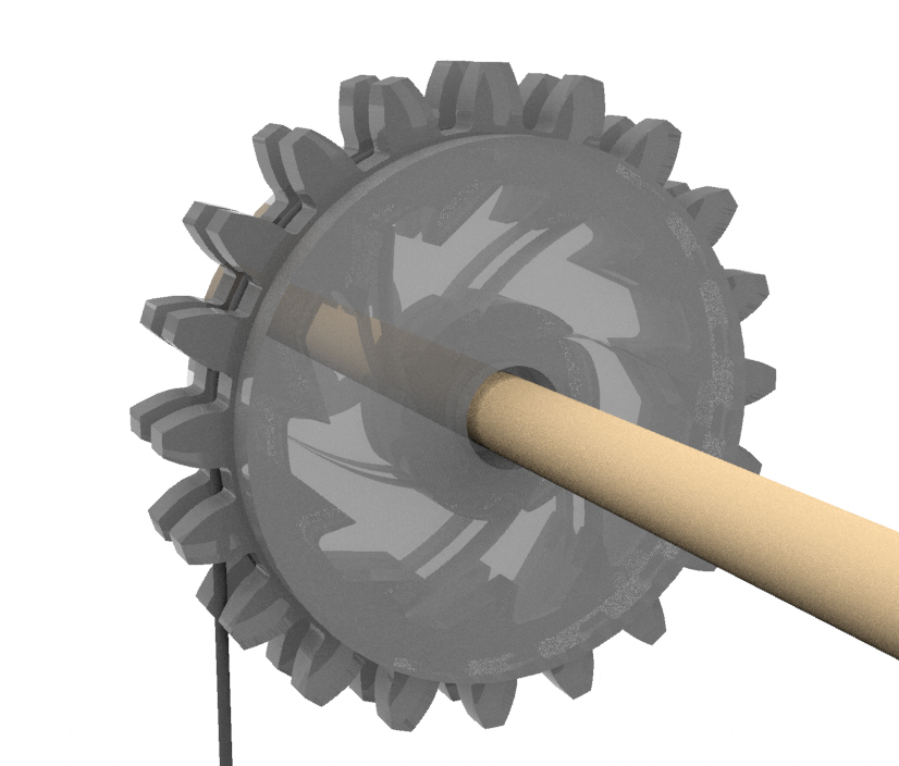
Gears
All the gears were created using a gear generator. There were a lot of restrictions I had to accommodate for:
- getting the right pair of gear ratios
- making some gears big enough to fit around the pipe axle
- making gears small enough so they didn’t hit other components
- minimizing size to save material
- making it strong enough to not break After several redesigns and trial and error I was able to get a set of working gears.